

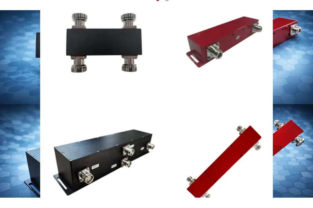
In the evolving landscape of 5G and high-capacity wireless networks, managing RF signals with precision is more critical than ever. The Hybrid Coupler (often referred to as a 3dB Bridge or Quadrature Coupler) is a cornerstone component in this domain.
This guide provides a deep dive into the mechanics, manufacturing, and strategic advantages of using Hybrid Couplers in modern RF systems.
1. Defining the Hybrid Coupler
In Radio Frequency (RF) and microwave engineering, a Hybrid Coupler is a specialized four-port directional coupler designed to split an input signal into two paths with a specific phase relationship and equal power.
At MS-TELERF, our hybrid couplers are engineered to provide equal 3dB power splits with high isolation, making them ideal for base station and Distributed Antenna System (DAS) deployments.
2. Working Principles
A hybrid coupler functions through electromagnetic coupling. When a signal enters the Input Port:
- Power Splitting: The energy is divided exactly in half (50%/50% or -3dB).
- Phase Shift: Unlike standard power splitters, the outputs maintain a fixed phase difference (typically 90° or 180°).
- Isolation & Protection: The fourth port, known as the Isolated Port, is terminated with a 50-ohm load. This port absorbs any reflected signals due to impedance mismatch, protecting the sensitive transmitter equipment.
3.90° vs. 180° Hybrids: Key Differences
| Feature | 90° Hybrid Coupler | 180° Hybrid (Rat-Race) |
| Phase Difference | Outputs are 90° apart | Outputs are 0° or 180° apart |
| Common Alias | Quadrature Hybrid | Magic Tee / Rat-Race Coupler |
| Primary Use | Power Combining, DAS, Balanced Amps | Mixers, Antenna Feed Networks |
| Input VSWR | Excellent (Reflections cancel) | Good |
4. Pros and Cons Analysis
The Advantages
- Superior Isolation: Provides high isolation (typically >20dB) between signal sources, preventing interference.
- Low VSWR: 90° hybrids naturally cancel reflections at the input port, ensuring a near-perfect 50-ohm match.
- Low PIM (Passive Intermodulation): MS-TeleRF air-dielectric couplers utilize premium plating to minimize noise in 5G/LTE bands.
- System Protection: Effectively directs reflected power to the dummy load rather than the RF source.
The Disadvantages
- Physical Size: High-power air-dielectric couplers can be bulky compared to simple resistive splitters.
- Cost: Precision CNC machining and silver plating make them more expensive than standard dividers.
- Requirement for Load: Must be paired with a high-quality termination load on the fourth port.
5. Manufacturing & Craftsmanship
The performance of a coupler is a direct result of its construction. At Ms-telerf, we utilize several high-end processes:
- Air-Dielectric Stripline: Suspends conductors in air within a CNC-machined aluminum housing. This is the gold standard for Low PIM (≤-161 dBc) and high power handling.
- Surface Treatment: We apply Silver Plating or Tri-metal (White Bronze) coating to ensure maximum conductivity and oxidation resistance.
- Microstrip Technology: Used for compact, lower-power applications where the circuit is etched onto high-frequency substrates like Rogers.
6. Core Application Scenarios
I. Neutral Host DAS (Distributed Antenna Systems)
In venues like stadiums or airports, hybrid couplers combine signals from multiple carriers (e.g., AT&T, Verizon) into a single antenna system without the signals interfering with one another.
II. Balanced Amplifiers
By splitting a signal with a 90° hybrid, amplifying each path, and recombining them, engineers achieve high redundancy. If one amplifier fails, the system remains online at reduced power.
III. Antenna Feed Networks
Hybrid couplers are used to feed cross-polarized antennas to create Circular Polarization, which is essential for satellite communication and reducing signal fading.
7. Selection Guide for Your System
When selecting a coupler on MS—TELERF, consider these three factors:
- Frequency Range: Ensure it covers 600MHz to 6000MHz for 5G FR1 compatibility.
- PIM Rating: For carrier-grade networks, always specify Low PIM (-161 dBc or better).
- Connector Type: Choose 4.3-10 connectors for modern 5G builds or N-Type for legacy systems.
Related article

1.Why Do You Need an RF Combiner? In field engineering, the biggest headache is often limited antenna space or the nightmare of …

1.How It Works: The Physics of Coupling A Directional Coupler is a fundamental passive RF component designed to achieve directional sampling of …